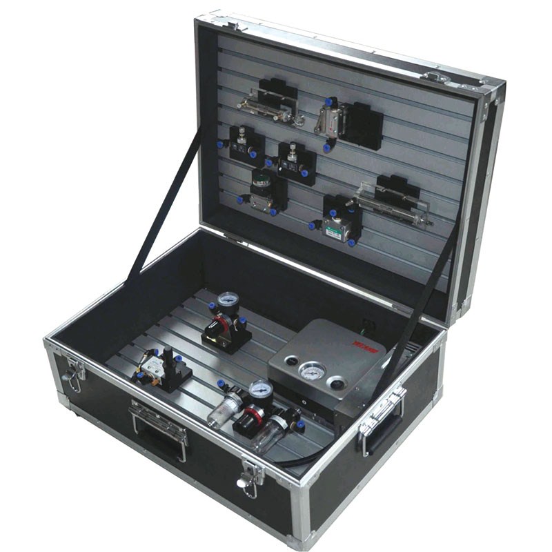
Capability
1.understanding of pneumatic components structure, signal and functions
2.reversing loop of push button valve controlled single acting cylinder
3.speed control loop of single acting cylinder
4.manual controlled reversing loop of hand directional valve
5.pneumatic controlled reversing loop of hand directional valve
6.speed control loop of double acting cylinder
7.speed control loop of throttle valve
8.seequential loop of two cylinders
9.reversing loop of OR gate valve controlled single acting cylinder
10.remote controlled unloading loop
11.push button valve controlled double acting cylinder loop
12.reducing valve controlled pressure-relief loop
13.two hands controlled single acting cylinder reversing loop
14.disassembly and assembly of hand directional valve(5/2way)
15.disassembly and assembly double pneumatic controlled 5/2 way valve
16.disassembly and assembly of throttle valve
17.disassembly and assembly of roller lever valve
18.disassembly and assembly of reducing valve
19.disassembly and assembly of push button valve
20.disassembly and assembly of OR gate valve
21.pneumatic simulation software
Component introduction function
Connection and operation tips
Manual connection function
Automatic connection function
Two-dimensional diagram pneumatic loop dynamic simulation
Two-dimensional diagram pneumatic loop dynamic simulation with stop/start function
Pneumatic loop schematic diagram, component dynamic inner structure display
Parameters
1.input voltage: AC200V ±10%, 50Hz
2.complete appliance capacity: 0.3kva
3.working temperature: -5℃~40℃
4.operating humidity: less than 90%(40℃)
5.dimensions: 580*430*240mm
If you have any enquiry about quotation or cooperation,please feel free to email us at erica_bell@163.com or use the following enquiry form. Our sales representative will contact you within 24 hours. Thank you for your interest in our products.
| Subject: | |
|---|---|
| Message: | |
| *Name: | |
| *Email: |
(Please make sure your E-mail address is correct otherwise the recipient will not be able to reply.) |
| Tel: |
(Please make sure your Business Phone is correct otherwise the recipient will not be able to reply.) |
| Fax: | |
| Address: | |
|
|


